If you have any questions, improvements, or corrections email me at the address at the bottom of the page.
The board was created using the KiCad software suite. See License file for license of this board and license information and attribution for included files.
The directory pdf has the board schematic (top.pdf) for the actual PCB layout. The corrections are described in the PCB errors.
The directory info has a spreadsheet of the BeagleBone Black (BBB) pins used, and the board license.
The directory bom has the bill of materials for building the board.
The directory datasheets has datasheets for the chips used.
The board is laid out such that it matches the normal drive connector locations and orientation when installed with the component side up. The BBB plugs into the bottom solder side of the board. The assembled height should allow installation in a half height 5.25" drive bay.
The mounting holes in the board match the standard 5.25" drive bottom mounting holes. If the drive being emulated was mounted with screws into the bottom of the drive the board can be mounted using standoffs. The board is shorter than a normal drive so the connectors will be further back.
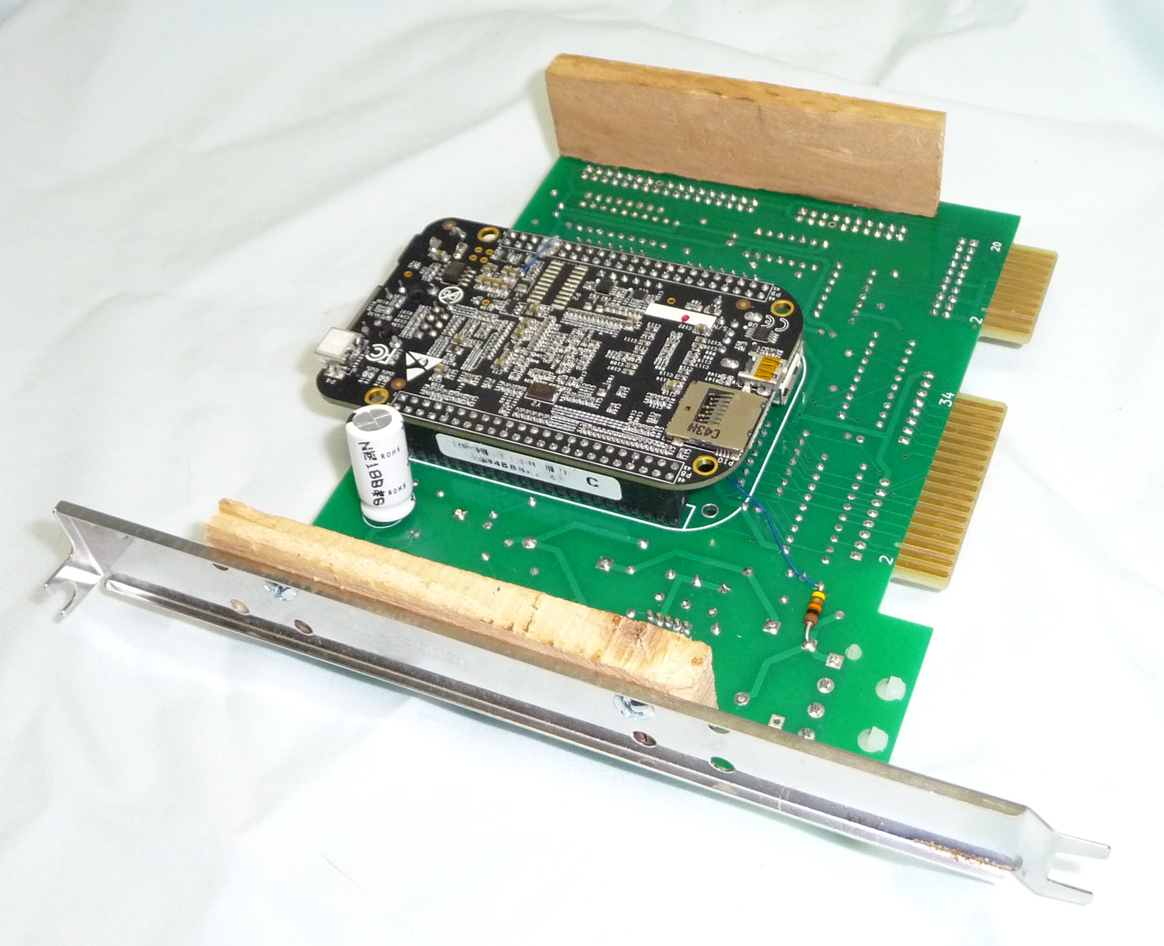
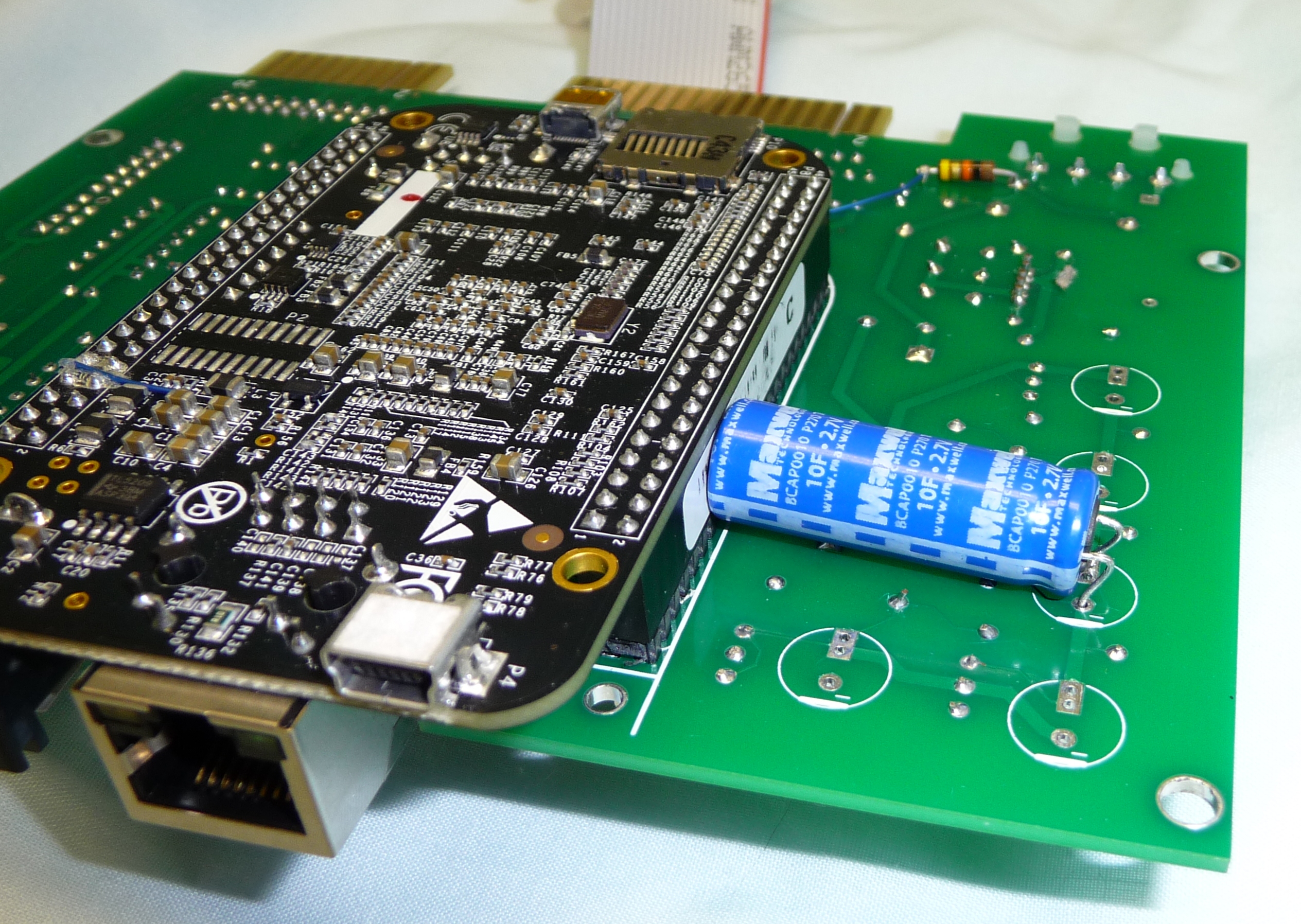
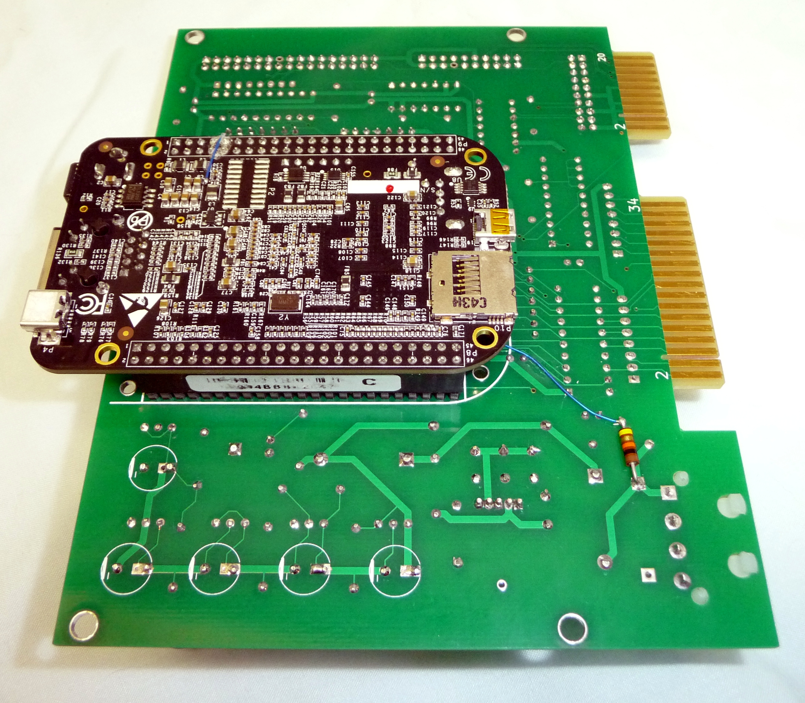
For drives that mounted using screws into the side, mounting blocks for the board will need to be made. Space has been left along the side of the board to allow the board to be screwed to the blocks using #6 screws and then screwed to mounting rails or the drive cage as needed. This is a partially assembled example with a mounting rail:
The J8/J9 connectors for the BBB (U1) should be installed on the back/solder size of the board with the short pins soldered to the board.
J6 is rotated opposite other components.
The capacitors C1-C5 may be installed on the side of the board that makes it fit better for the mounting method chosen. With the 5F caps on the top, the assembled height is only slightly smaller than a half height drive so the board mounting will need to be accurate to fit. With the capacitors on the bottom the height is less which may make it easier to mount.
 The 10F caps have plenty of space mounted on either side when installed
in a full height drive bay. If you wish to use them in a half height
drive bay they will need to be installed laying down. Only four have
room to do that cleanly. My origional instructions were C5 will need to
have wires run from the pads to the capacitor which should be able to go
near J5/U12. Do it first then install the others over its wires.
You can bend the leads to install the other capacitors. I recommend holding the lead with needle nose pliers when bending to avoid stressing the capacitor
seal. I would use RTV silicone to
attach the capacitors. Use a non-acetic-acid cure (that doesn't
smell like vinegar) to prevent corrosion. If you are buying from a distributor
it will be listed as suitable for electronics. The consumer GE silicone II
caulk is also OK.
The 10F caps have plenty of space mounted on either side when installed
in a full height drive bay. If you wish to use them in a half height
drive bay they will need to be installed laying down. Only four have
room to do that cleanly. My origional instructions were C5 will need to
have wires run from the pads to the capacitor which should be able to go
near J5/U12. Do it first then install the others over its wires.
You can bend the leads to install the other capacitors. I recommend holding the lead with needle nose pliers when bending to avoid stressing the capacitor
seal. I would use RTV silicone to
attach the capacitors. Use a non-acetic-acid cure (that doesn't
smell like vinegar) to prevent corrosion. If you are buying from a distributor
it will be listed as suitable for electronics. The consumer GE silicone II
caulk is also OK.
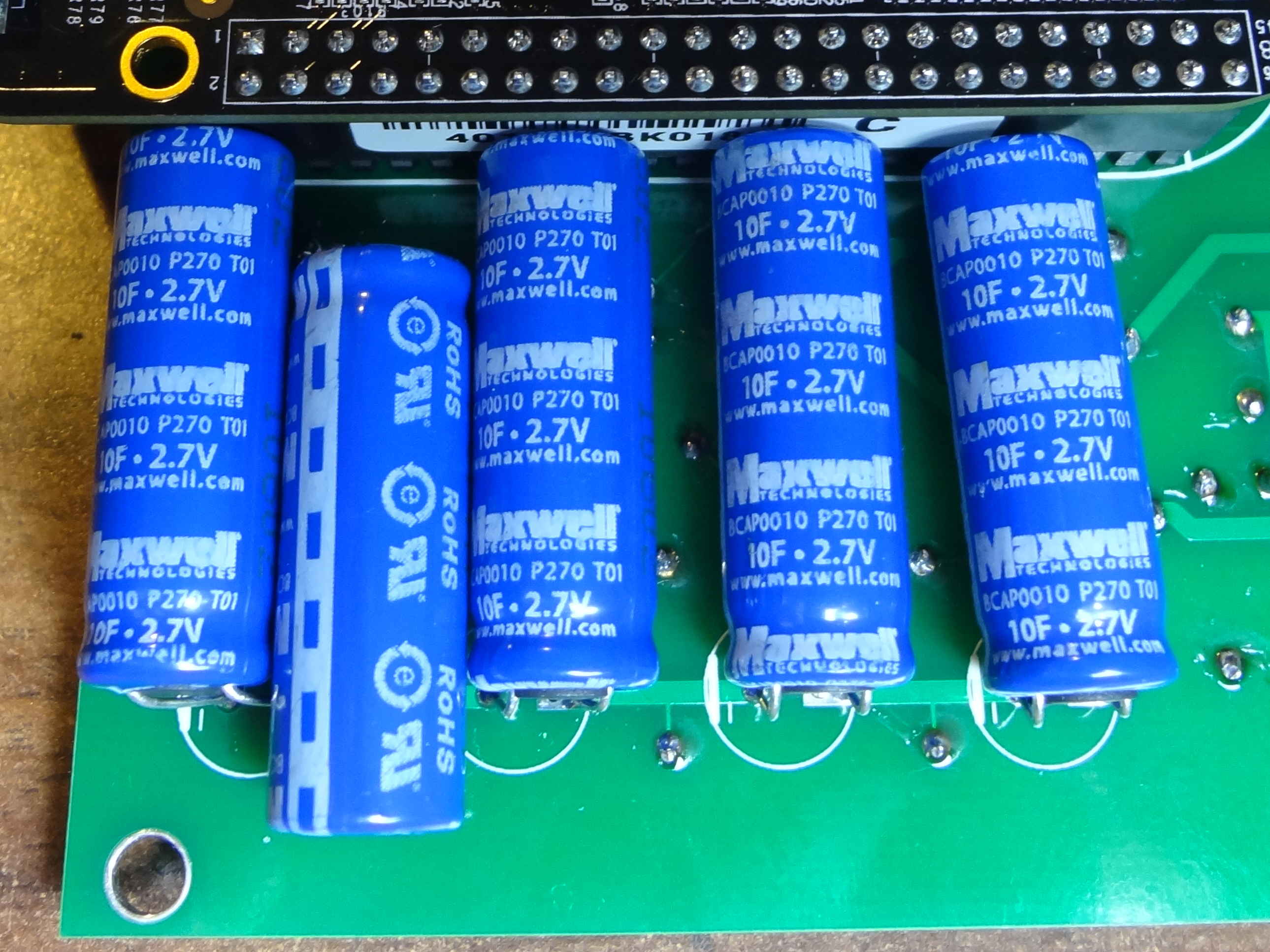
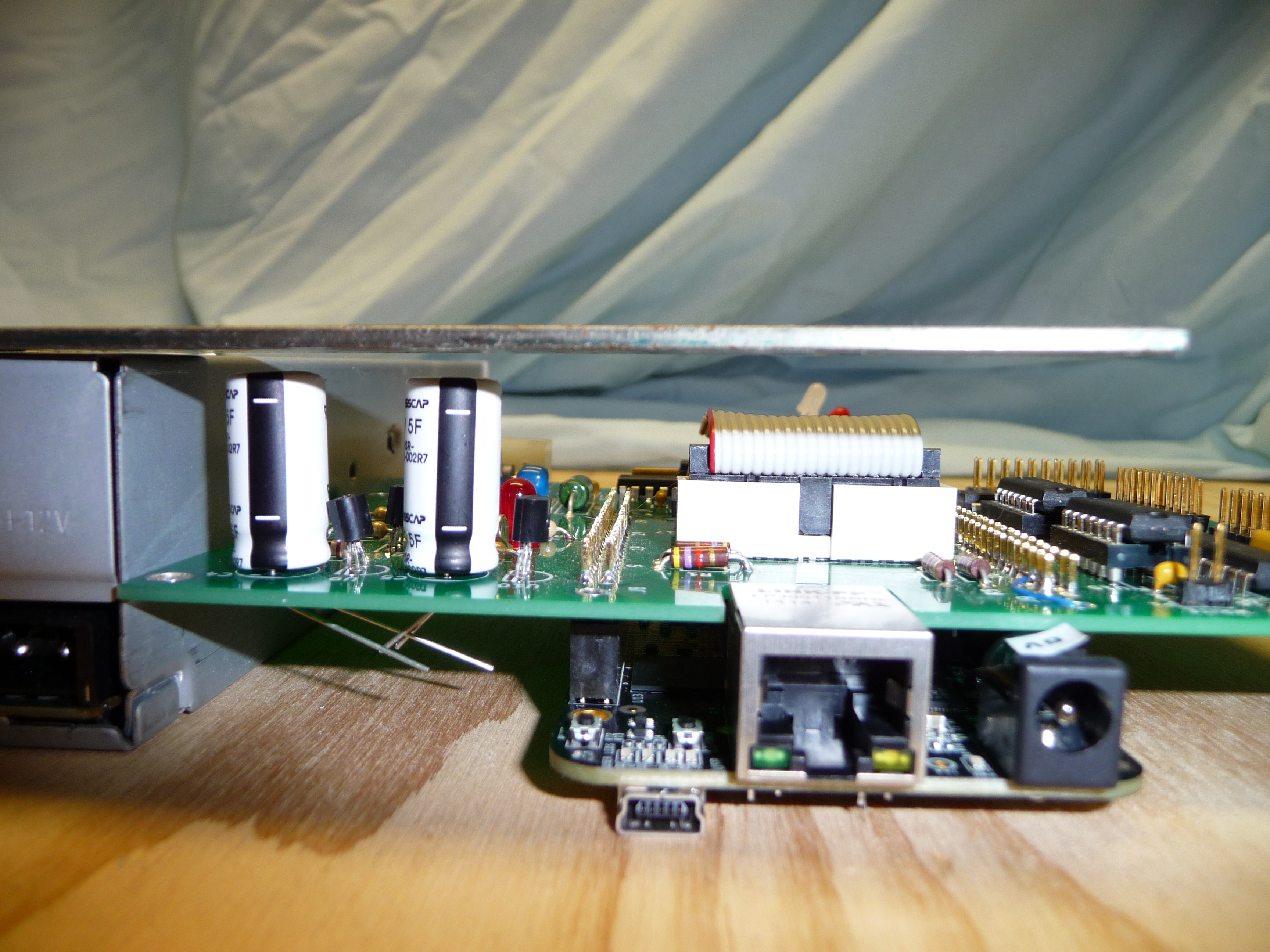
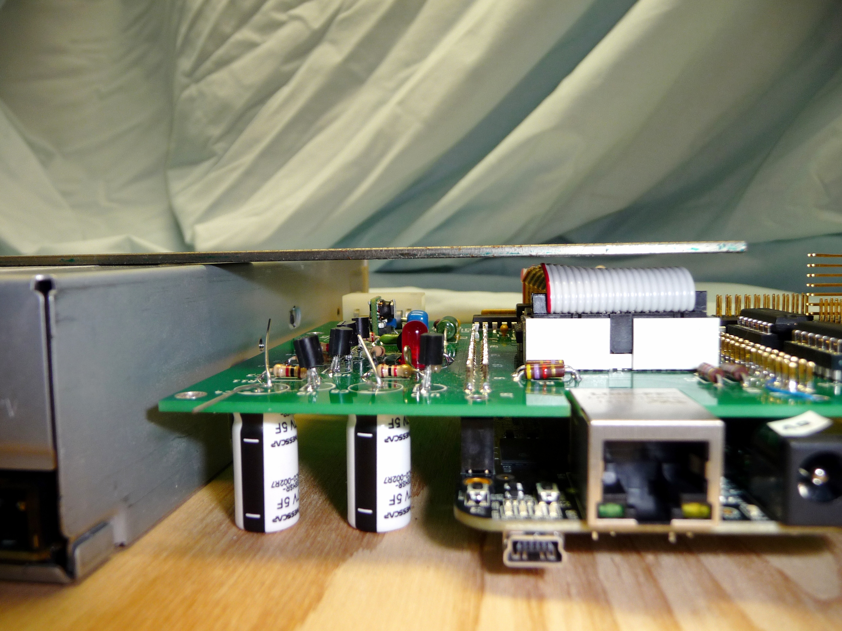
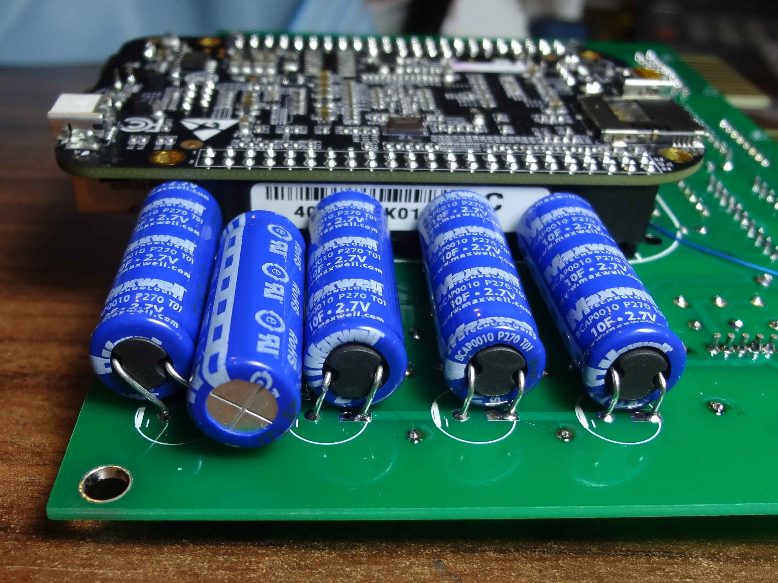 Steven Hirsch sent me these pictures showing that he was able to install all the
capacitors lying down close to the normal locations just using the leads.
Steven Hirsch sent me these pictures showing that he was able to install all the
capacitors lying down close to the normal locations just using the leads.
The cables mating to J4 frequently have pin 15 plugged for polarization so you may wish to remove that pin before installing the connector.
The cables mating to J3 and J6 frequently have pin 8 plugged for polarization so you may wish to remove that pin before installing the connector.
The primary part DC/DC converter U12 is not marked clearly with which pin is 1. See assembled picture at the top of page and below for correct orientation. Also due to the close lead spacing watch out for shorts when soldering.
Read the assembly options section below to decide what components you wish to populate.
Verify the rework needed has been done to the board and decide what size capacitors if any you wish. Also see the J7 connector discussion for J7 part selection and LDO03C undesired behaviors for U12 part selection.
Use the Bill of materials to order the components to build the board. I used Digikey and Mouser though other distributors are likely to have suitable parts. The BBB currently is in short supply. This page has links to distributors. Note that some are charging more than list or only will sell single units. If you are using it for disk reading and not emulation you may wish to buy a 5V power supply that connects to the BBB barrel jack with the BBB.
After you get the parts I installed parts by height so when the board is flipped to solder they get pressed against the board. I started with the 1/4 W resistors values with low quantity, then the 1k which are near the big capacitors and then the 5.11k in remaining spots. The holes are .4 inch spacing if you have a lead bender. If you spread the leads they won't fall out when you flip the board. I install some components then solder before they start getting in the way of soldering then repeat. A reasonable order for the rest is F1, .1 capacitors, IC's, RN1-RN3, R13, other small capacitors, P1, P4, J3, J4, J6, J7, J5, U6-U10, D1, D3, D2, U12, J8, J9, C1-C5. You may use what works for you. Be careful of component orientation. Sockets XRN1 and XRN2 are suggested for RN1 and RN2 so the terminating resistors can be removed if the emulator is used on the same cable as another drive that has terminating resistors installed. The last drive on the cable is supposed to be terminated and others not terminated. J5 installs easily if you first put the plastic tabs through the board and push it forward so you can get the rear pins in.
Install the jumper wire between R16 and J9 pin 34. If you didn't solder it when installing J9 solder the wire from the added chip to J9-9.
After you are done inspect the board for shorts,
unsoldered leads, components installed with incorrect orientation, missing
components etc.
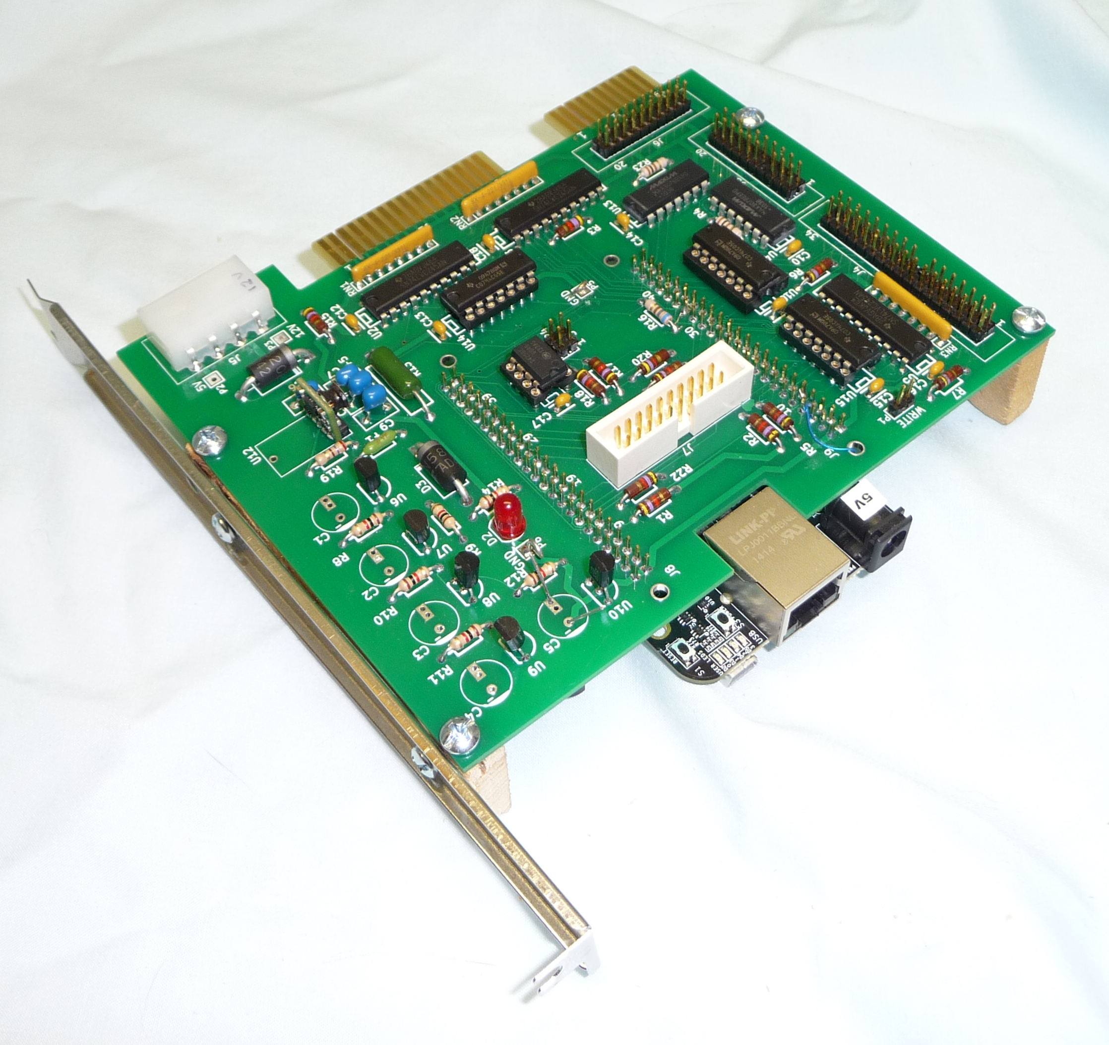
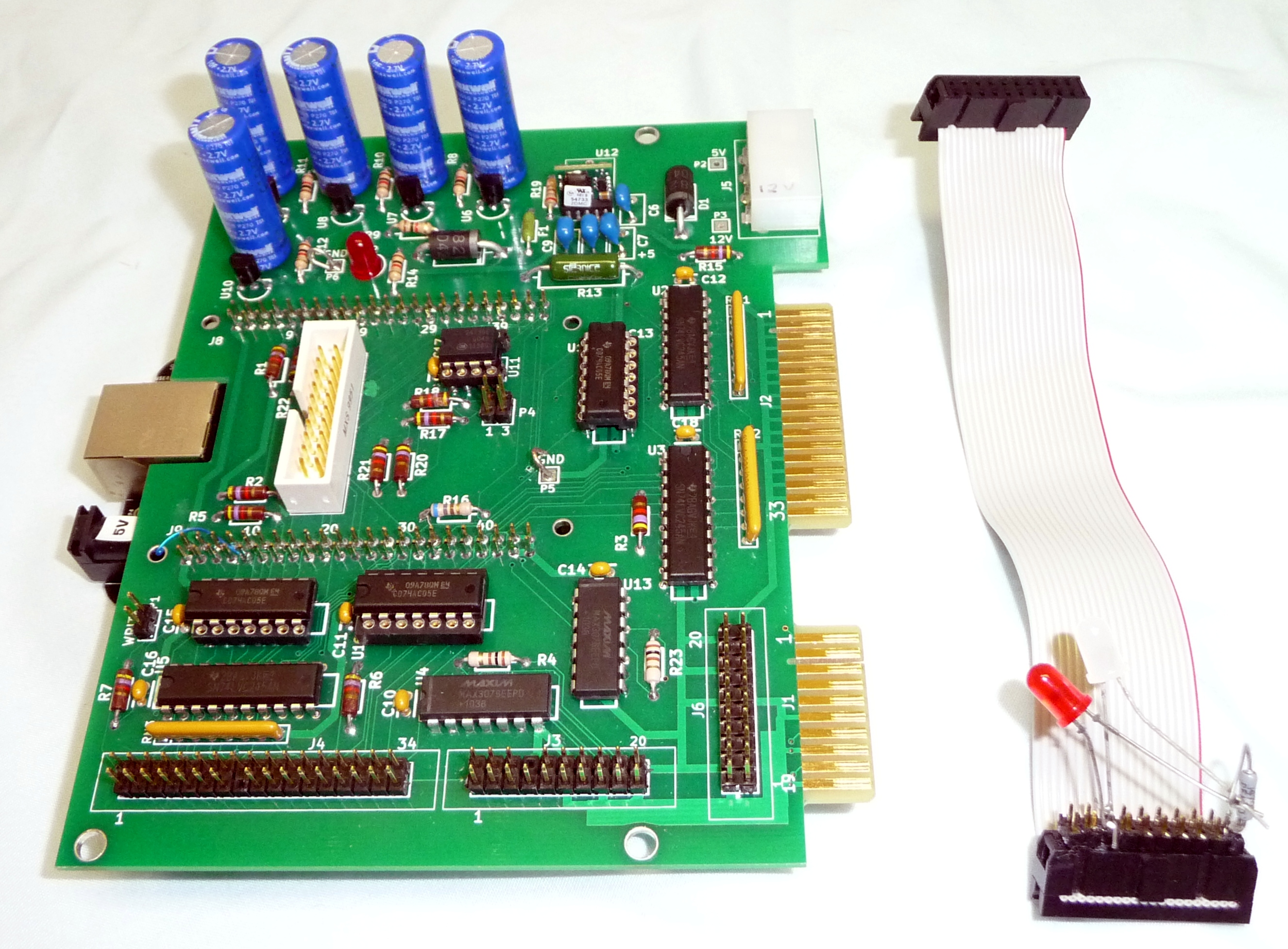
It should look like this assembled board.
The cable was for testing the drive activity LEDs. A couple parts
such as J7 are parts I had around and not what is called for in the
parts list. A couple chips are also socketed for my testing.
If you are using a console image you will need to install some packages as follows
apt-get update
apt-get install gcc make am335x-pru-package binutils-dev device-tree-compiler
I have updated my BBB rev B to BBB-eMMC-flasher-2013.09.12.img.xz from here and then did opkg update and opkg upgrade to bring it to the latest software versions. uname says it's running kernel 3.8.13. Other versions probably will work.
You should Install the software before trying to test with the MFM board.
If you installed U12 power up the board without the BBB and verify the 5V is correct. Then install the BBB and verify with ohm meter that R16 jumper wire is shorted to P5 ground.
Power up board. With the MFM board installed the power must be supplied from the MFM board power connector J5 or if U12 isn't installed the barrel power jack on the BBB may be used. Ssh into the BBB. I use the Ethernet though the USB port should also work. Under Debian (rev C boards) the Ethernet only does DHCP if the cable is connected at power up. If the cable is disconnected at power up or later it does not request an IP address.
If you installed the holdup capacitors first try the powerfail command.
echo cape-bone-iio > /sys/devices/bone_capemgr.*/slots
cd ~/powerfail
./powerfail --debug --powercmd true --threshold 0
It should print after several seconds something like
Average 12.27V max 12.30V min 12.24VControl-c it after it prints the message. Verify the voltage matches the input voltage and min to max difference is reasonable for your supply ripple. For more information see the command documentation.
To test the PCB rework added chip ssh into the BBB and enter the command:
poweroff -fThe board should power down then immediately power back on.
If you really wish to power off the board you need to remove the 12V either before or during the poweroff. I also use halt -f then remove the 12V when I'm shutting down the board which halts but doesn't power off the board. Someone decided to be "helpful" and do poweroff when you use the halt command unless you specify -f. The -f triggers a bug where you will get some error messages that don't seem to effect anything. -f also prevents running the shutdown scripts.
To test disk reading attach cables from J3 and J4 to a drive and power
up the board and drive. Note that setup_mfm_read only needs to be done
once per boot. For now you need to reboot the board to switch between
reading disks and emulating.
cd ~/mfm
./setup_mfm_read
./mfm_read  --analyze --emulation_file ../emu_file --extracted_data_file filename
   or
./mfm_read --emulation_file ../emu_file --cylinders # --heads # --drive #
If you specify the extracted_data_file the program will retry on read error and report uncorrectable errors. This way you get the best emulation file and know where the errors are. If analyze doesn't understand your drive format use the second command where you will need to specify the number of cylinders, heads, and which drive select your drive is on.
If you get "Unable to find drive. If just powered on retry in 30 seconds" it didn't see the drive selected signal come back when it raised any of the drive select lines. If your drive had a light did it come on? If you have test equipment test J4 pin 26, 28, 30, and 32 are being driven low and see if the drive responds by pulling J3 pin 1 low.
I have found with some drives that if you are getting read errors reorienting the drive may get rid of them. I normally start with lying flat then try on the sides.
I have found that with Seagate ST-251 drives if I am getting read errors that if I push on the shaft of the head stepper motor during the retries most of the time it will get a good read. This may work with other drives with external stepper motors. I first do a read without touching anything in case it damages the drive. Then I increase the retries and position the drive so I can touch the shaft. When I hear it retrying I put a little pressure on the shaft and hopefully it will say all sectors recovered. If I press too hard I get seek errors. The program will recover from seek errors.
For more information see the command documentation.
To test disk emulation attach cables from controller to J1 and J2. Power up
board and run the following if you previously read the drive you wish to
emulate. Note that setup_emu only needs to be run once per boot.
cd ~/emu
./setup_emu
./mfm_emu  --drive 1 --file ../emu_file
If the drive you wish to emulate isn't on drive select 1, change to desired number on the command. Then try to boot the computer attached to the drive emulator or access the emulated disk drive. The mfm emulator should print messages like shown in the documentation and the computer should act like it has the disk attached.
If you didn't read a disk to emulate you will need to start with an unformatted drive:
cd ~/emu
./mfm_emu  --drive 1 --file ../emu_file --initialize --cylinders # --heads #
If the drive you wish to emulate isn't on drive select 1 change to desired number on the command. Replace # with the proper numbers for the drive you wish to emulate (you don't need number of sectors). Then run the low level format command on the computer attached to the drive emulator. The mfm emulator should print messages like shown in the documentation and the format should complete without errors.
If the seek time other than the first printed is zero the updated am335x_pru_package-master was not correctly installed when building.
For more information see the command documentation.
.You need to increase the shared memory size for the PRU. Do the following commands:
ssh root@ipaddr
echo options uio_pruss extram_pool_sz=1048576 > /etc/modprobe.d/uio_pruss.conf
exit
The MFM board uses pins that are used by the HDMI audio and the expansion connector J7 uses pins that are used for HDMI video. This requires that the HDMI interface be disabled. I give instructions for doing it with ssh. You can use the HDMI video to do it to have a graphical editor to make the changes.
To do this for a rev B Angstrom board
ssh root@ipaddr
mkdir /mnt/temp
mount /dev/mmcblk0p1 /mnt/temp
vi /mnt/temp/uEnv.txt
  add to the end of the line capemgr.disable_partno=BB-BONELT-HDMI,BB-BONELT-HDMIN to get
   optargs=quiet drm.debug=7 capemgr.disable_partno=BB-BONELT-HDMI,BB-BONELT-HDMIN
   and then save file
umount /mnt/temp
reboot
For a rev C Debian
ssh root@ipaddr
vi /boot/uboot/uEnv.txt or /boot/uEnv.txt if previous file doesn't exist. The
location was changed in later Debian images
  Uncomment cape disable line to as shown below
  ##Disable HDMI
  cape_disable=capemgr.disable_partno=BB-BONELT-HDMI,BB-BONELT-HDMIN
  and then save file
reboot
I used vi for editing files. If you haven't used vi there are manuals online. Here is one. To do the above changes type /cape_disable to take you to the start of the first cape disable line. Hit n to go to the next matching line until you are at the correct line. Then type h to move to the # then type x to delete the # then type :wq to save the file.
You may use any editor. The nano editor may be easier to use if you are not familiar with vi.
You can also copy off the file to another system to edit and copy back. It appears that USB sticks are only mounted if they are present at boot.
The image that comes with the BeagleBone has bugs in the library for accessing the PRU coprocessors. On this page is the current version that works. Download the files as a Gzipped Tar file Copy it to the BBB and build:
scp master root@ipaddr:
ssh root@ipaddr
tar -xzf master
mv beagleboard-am335x_pru_package-* am335x_pru_package-master
cd am335x_pru_package-master
make
exit

   If the BBB has Internet access you can also use
wget https://github.com/beagleboard/am335x_pru_package/tarball/master
   to download directly on the BBB.  Then do above from tar.
   or
git clone https://github.com/beagleboard/am335x_pru_package.git
   to clone repo. Then do above from cd.
Install the libiberty library. Instruction for Debian:
apt-get update
apt-get install binutils-dev
If your beaglebone doesn't have internet access you can download the file from https://packages.debian.org/wheezy/armhf/binutils-dev/download copy to beaglebone and install with
dpkg -i binutils-dev_2.22-8_armhf.debDownload latest mfm code .tgz file and copy it to BBB and build.
scp mfm_emu_powerfail*.tgz root@ipaddr:
ssh root@ipaddr
tar -xzf mfm_emu_powerfail_*.tgz
cd mfm
make
cd ../emu
make
cd ../powerfail
make
exit (or poweroff)
When making mfm and emu the first line printed should be
"Using local copy of am335x_pru_package"
if it found the installation of am335x_pru_package-master.
The board has capacitors to provide power for a short time when power is lost to perform a clean shutdown of the operating system. This prevents corruption of the flash memory or data loss. If this is not desired don't install the following components: C1-C9, U6-U10, R8-R16, R19, D1-D3, F1, and U12. Connect P2 (5V) to the 5V side of C7. You may wish to install C8 for bulk decoupling.
If the ability to read an existing disk is not desired don't install components C11, C16, J3, J4, P1, U5, U16, R5, R6 and RN3. If both reading a second disk and emulating a second drive is not desired don't install components U15 and C15.
If drive emulation is not desired don't install components U2, U3, U14, RN1, RN2, XRN1, XRN2, R2, R3, C12, C13, and C18.
If second drive emulation is not desired don't install C14, U13, J6, R3, and R23.
If BBB shield auto identification of pins used is not desired don't install U11, P4, R17, R18, and C17. R20 and R21 can also not be installed if I2C is not used on J7. Programming the EEPROM is at least as difficult as setting up a script to perform the configuration at boot so it's probably not worth installing these components.
LED D2 is used to warn that the capacitors are still charged. If this is not needed don't install D2 and R14.
If expansion signal connector is not desired don't install J7.
Parts were chosen to be available at Digikey and Mouser. If a part was available from both it was chosen otherwise an alternate part is shown in the parts list. You may be able to substitute parts with the particular distributor you are using to get lower price.
For the headers both shrouded and unshrouded headers are listed. Use the type you like. The gold plating thickness varies on the parts listed. Minimum is 10 microinch (uin) gold or 30 uin GXT gold. If thicker plating is desired to allow many unmating cycles other parts may be chosen.
For DC/DC converter U12 the primary part requires the external capacitors C6-C9. The datasheet for the secondary part LDO03C says it does not require external capacitors though does recommend a 1 uf input capacitor. The capacitors on the parts list can be installed for better filtering. Other options would be one of the 10 uF for the input and output or just put the .1's in for C6-C9. With this board version the secondary part is not recommended.
I have purchased many of the parts to verify the parts list is correct but not all. You may wish to check headers and alternate parts before purchasing.
For reading an existing drive connect it to J3 and J4. Jumper P1 if writing to the drive is desired. Currently the software does not support writing to a drive. See the usage information in Board checkout.
For emulating a drive connect the control cable to J2 and data cables to J1. To emulate two drives connect the second data cable to J6. This will only work if the system shared the control cable between the two drives being emulated. See the usage information in Board checkout.
J7 is for connecting operator controls or status displays. No software support is currently provided. Any I/O must be 3.3V to prevent damage. See board design notes for more information.
If you wish drive emulation to automatically start on boot for Debian edit /etc/rc.local and add the lines:
cd /root/emu
./setup_emu
for i in $(seq 1 10); do
   if [ -e /dev/uio1 ]; then
      break
   fi
   sleep 1
done
nohup /root/powerfail/powerfail --powercmd "poweroff -f" --command "/root/emu/mfm_emu --drive 1 --file /root/emu_file" > /dev/null 2>&1 &
Modify command line as needed. If the chip to power back on the board was not added during the rework use halt instead of poweroff. It seems to take about 18 seconds from power on until the mfm emulator is running.
If things don't start change the command to the following and see the messages in /tmp/cmdout.
nohup stdbuf -o L -e L /root/powerfail/powerfail --powercmd "poweroff -f" --command "/root/emu/mfm_emu --drive 1 --file /root/emu_file" > /tmp/cmdout 2>&1 &Above can be useful also if you wish to see the output of the running emulator. If you install reptry (apt-get install reptyr for debian) you can then attach to the running process with the following. Using
reptyr -s `ps -C mfm_emu -o pid=`Without the stdbuf the output will be delayed by output buffering.
The board may be powered through the drive power connector J5 or the BBB barrel power jack. It can't be powered by the USB connector.
The board has a bank of super capacitors to provide enough power to allow the software to cleanly shut down the BBB operating system when power is lost to prevent file system corruption and data loss. The board input is 12V with a DC/DC converter to generate 5V. If the backup power is not desired a pad is provided to allow the input 5V to power the board instead of the DC/DC converter.
The BBB takes around 350 mA running and the emulation board fully populated is expected to take around 300 mA for total of .650 A/3.25 W. It is expected that the capacitors should be able to run the board for at least 7 seconds after power is lost.
The capacitors are rated at 2.7V maximum. With 5 in series the theoretical rating is 13.5V. Due to mismatch in capacitance when charging the voltage will not divide evenly between the capacitors. U6-U10 clamp the voltage on each capacitor to 2.5V. With .3 volt drop across D1 the 12V input should be below 12.8 volts to prevent the entire string of regulators trying to clamp the input voltage. Resistors R8-R12 prevent the mismatch in capacitor leakage current from unbalancing the voltage on the capacitors.
R13 sets the peak charging current and limits current through voltage clamps on capacitors. The 10 ohm resistor sets peak current to about 1.2A. The value was picked such that if the capacitance of one capacitor is 20% greater than others, it will keep the current through the voltage regulator under the maximum rated current. Adjust the value if a different peak charging current is desired. Make sure the part chosen can withstand the peak power dissipated. With this resistor it will take about 70 seconds to charge the capacitors to 90% of final voltage.
Super capacitors were chosen since they are expected to be much more reliable than batteries though it does increase the cost. As an alternative some people have attached a battery to their BBB. Since when on battery 5V won't be provided to the termination resistors all the control lines will go low. This can be interpreted as a write. Switching RN1-RN3 to 150 ohm bussed resistors powered by 3.3V will prevent this. This will require cuts and jumpers. I have not tried the battery method of powering the board. There are other options such as a push button to shut down or if nothing is important on the drive reflashing the beaglebone if the flash gets corrupted.
J7 is provided to allow switches for controlling operation or displays for status. See J7 Expansion connector for drive select LED implementation. Other usage needs to be implemented by user. For my usage I only desire to select between a few images. I am planning to hook up a rotary switch that I can use to select the image at boot time. I was also going to see if a wireless USB adapter gets enough signal inside the chassis. This will allow me to back up the emulation image and any other playing I wish. The USB connector ended up in a bad location so a short extension cable may be needed to get the USB WIFI closer to an opening for better reception.
The expansion connector uses the LCD pins so LCD/HDMI video will not work if the expansion connector is used. I suspect it won't work even if it's not used due to the additional loading and that the MFM portion of the design uses the audio pins.
All signals must be 3.3V. 5V and 3.3V power is provided. With cuts and jumpers the unused pins on U2 and U3 can be used to level shift signals. Also note that expansion 10, 11, and 12 are on pins used to select boot device. These pins have 100k resistors to +3.3 or ground. Anything connected to them must ensure they still have valid logic level at power up either by limiting loading or with a lower value resistor. See the BBB system reference manual for interfacing information.
The write jumper P1 when removed ensures software errors can't cause writing to a drive being read. R7 prevents the write line from being seen as a low if the termination is not installed on the drive if this board is powered from the same supply powering the drive. Its value is high enough that it will not load down the write signal if this board is powered off while the drive still has power.
The EEPROM for shield configuration was designed in the board. Shields that are sold pre-assembled are supposed to have the EEPROM. It's not really useful for kit boards.